Rock Sand Machines to Be Connected by Bolt
- Submitted by: wanerjob
- Views: 247
- Category: History: Middle Eastern
- Date Submitted: 08/19/2014 07:53 PM
- Pages: 2
- Report this Essay
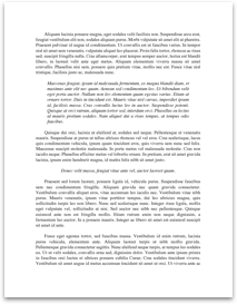
Pipe 24 is inserted into larger trepanned hole 26 to provide equal passages through the pipe 24 and around its circumference. Collar 28 is welded to pipe 24 and ring 30 is attached to provide a watertight barrier when pipe 24 is threaded or otherwise affixed to roll core 6. Water is introduced into pipe 24 and channeled to radial passages 34 and thence to annular grooves 36 which functions as a supply manifold. The holes 38 are drilled into cover plate 40. In FIG. 3,rock sand machine an exploded view of two opposed clamps and the manner of fitting on a segment is shown. The clamps 4 may be seen to be connected by bolt 18. Between them is a roll segment 2 which contains pockets 54. This assembly, as the previously described roll assembly, is conventional except for the water circulation elements described below. Operation of my invention is illustrated as follows.
Water flows through holes 38 from groove 36 to holes 42 in clamp ring 4. The holes 44 channel water into holes 46 then through holes 48 in segment 2. Water flow is through segment 2 into outlet clamp 4, further into outlet annular groove 50 which operates as a discharge manifold, thence to radial passage 52. It can be seen that the water exiting through the trepanned hole 26 does not intermix with the inlet water inside the pipe 24. A divided flow of cooling water is directed in a once through passage 48 inside the segments 2 to cool the segment surfaces 54. Pipe 24 rotates with the roll; water is introduced to it from a conventional rotary joint not shown. If it is desired for the pipe to be stationary, a conventional rotary joint may be used in the interior of the roll.
A unique design feature of my invention is the manner in which the clamp rings 4, segments 2 and roll body 6 are gasketed at 56 and 58 as shown in FIGS. 4 and 6. FIG. 5 shows the obround gasket 58 inserted in retaining groove 60. FIG. 6 shows the obround gasket 56 and 58 in operating attachment with clamp 4, tightened against roll...